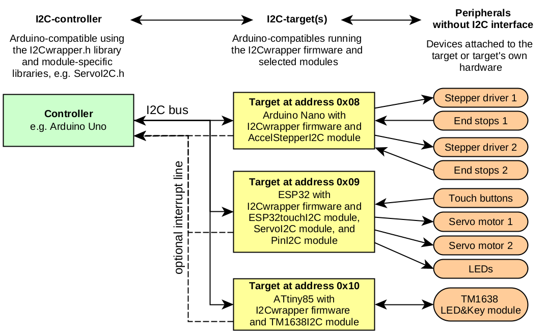
I2Cwrapper enables you to connect peripherals without dedicated I2C interface like stepper motor drivers, TFT-displays, sensors, etc. to an I2C-bus. It uses an Arduino-compatible device which acts as I2C target device(1) and "translates" between the I2C-bus and the non-I2C peripheral (see supported platforms). To do so, the IC2wrapper framework "wraps" library function calls and return values and transmits them between I2C-controller and I2C-target. From the controller's perspective, using the device over I2C is very similar to directly using it, so that existing code can be adapted with little effort.
The I2Cwrapper core consists of an easily extensible firmware framework and the I2Cwrapper.h controller library. Together, they take care of the overhead necessary for implementing an I2C target device, while the actual target functionality is delegated to device-specific modules.
This is a possible example setup:
(1)I2Cwrapper uses the current I2C terminology which replaced master with controller, and slave with target.
Download I2Cwrapper on github.
The I2Cwrapper library and the module libraries are documented here.
See Usage for a quick start.
Ready to use modules
Currently, the following modules come shipped with I2Cwrapper in the firmware subfolder. Note that not all modules will run on all platforms. See Available modules for more detailed information.
- AccelStepperI2C: Control up to eight stepper motors with acceleration control via Mike McCauley's AccelStepper library, and up to two end stops per stepper. Uses a state machine and an optional controller interrupt line to prevent I2C bus clogging.
- ServoI2C: Control servo motors via I2C just like the plain Arduino Servo library.
- PinI2C: Control the digital and analog in- and output pins of the target device via I2C, similar to an IO-expander. Works just like the plain Arduino pinMode(), digitalRead(), etc. commands.
- ESP32sensorsI2C: Read an ESP32's touch sensors, hall sensor, and (if available) temperature sensor via I2C. Uses the optional controller interrupt line to inform the controller about a touch button press.
- TM1638liteI2C: Read buttons from and control the single and seven-segment LEDs of up to four TM1638 modules like the ubiquitous LED&Key module via I2C. Uses Danny Ayers' TM1638lite library.
- UcglibI2C (new in v0.5.0): Control TFT and other displays with ST7735, ILI9341, PCF8833, SSD1351, LD50T6160, ILI9163 driver chips supported by Oli Kraus' Ucglib library over I2C.
While the setup for these modules differs from their respective non-I2C counterparts, usage after setup is very similar, so that adapting existing code for I2C remote control is pretty straightforward.
If there are no intrinsic resource conflicts, one or more modules can be selected in any combination at compile time for a specific target (see below for details). It is easy to add new modules with help of the provided templates.
v0.3.0 introduced additional feature modules. They don't act as interfaces to some peripheral, but can be used to add functionality to the target, such as an I2C-status LED, or implementing different methods of retrieving the target's own I2C address, e.g. from hardware pins or flash memory/EEPROM.
Basic components
The I2Cwrapper framework consists of four basic components. The first two drive the I2C target device:
- A firmware framework for the target device, implemented in the
firmware.inosketch. It provides the basic I2C target functionality:- onReceive() and onRequest() interrupt service routines (ISRs) which listen and react to the controller's transmissions,
- a command interpreter which processes the controller's commands received by onReceive() (in traditional I2C hardware this is equivalent to register writes and reads),
- an output Buffer which allows the target to prepare a reply which will be sent upon the next onRequest() event,
- transmission error control with CRC8-checksums,
- different ways for setting the target's I2C address: fixed address; EEPROM stored; and ~~(not implemented yet)~~ read from hardware pins,
- a controller interrupt mechanism which modules can use to alert the master proactively,
- triggering a target reset (i.e. re-initialization to initial state).
- Firmware modules which implement the actual functionality of the target device, e.g. controlling stepper and/or servo motors, or reading sensors.
- Modules exist as separate include files, e.g.
ServoI2C_firmware.h, and are selected for compilation via thefirmware_modules.hfile. - Modules don't have to worry about the I2C overhead but can concentrate on what's important: interpreting and reacting to the controller device's commands and requests.
- A module's main job is to interpret and react to commands passed to them from the controller through the firmware framework.
- Modules can "inject" their code at different places in the firmware (e.g. setup, main loop, command interpreter), so that there is a high degree of flexibility.
- Modules exist as separate include files, e.g.
The other two basic components are for the I2C controller's side:
- The I2Cwrapper class, provided by the
I2Cwrapper.hlibrary.- Controller sketches use an object of type I2Cwrapper to represent the target device which handles all low level communication tasks like CRC8 checksums, error handling etc.
- It also provides basic functions for target device management like changing its I2C address, setting an interrupt pin, or making it reset.
- Controller libraries for each module, e.g.
ServoI2C.h.- Controller libraries use I2Cwrapper objects to talk to the target device (like the
ServoI2Cclass inServoI2C.h). - They implement an interface for the respective target functionality, which transmits function calls to the target device, and receives the target's reply, if the command was asking for it.
- In the simplest case, they closely mimick the interface of an existing library (like Arduino
Servo.h) which is used on the target's side to drive the actual hardware.
- Controller libraries use I2Cwrapper objects to talk to the target device (like the
Limitations
Limitations for end users
- Arduinos aren't perfect I2C target devices. Not all Arduino hardware platforms have dedicated I2C hardware, which entails possible performance issues (see Supported platforms).
- The Arduino's Wire library doesn't support clock stretching in a way which allows the target to finish reacting to the previous command if it hasn't done so yet before the transmission occurred. That's why it's important to make sure that the target is not flooded with commands or requests with too little time to handle them. I2Cwrapper provides an adjustable minimum delay between transmissions which can help with that problem.
Limitations for module authors
- No serialization protocol is used at the moment, so the implementation is machine dependent in regard to the endians and sizes of data types. Modules will have to take care that transmitted commands and requests will transmit defined amounts of bytes by using typeguards for ambiguously sized datatypes like int.
- Modules use one byte command codes (similar to conventional I2C-registers) for each distinct function call to the target. At the moment, no mechanism is in place to prevent newly developed modules from reusing codes already used by another module or by one of the I2Cwrapper core functions. Note that this will only lead to problems if two conflicting modules are used concurrently by a target device. The I2Cwrapper documentation has a list of code ranges used by the currently available modules. Strictly reserved ranges are 0-9 and 240-255.
- The I2C buffer size used by I2Cwrapper objects defaults to 20 bytes. The CRC checksum takes 1 byte, the command header for transmissions from controller to the target take 2 bytes. That leaves 17 bytes as maximum parameter payload for commands and 19 bytes for target responses. A more flexible approach is planned for a future release. Note for ATtiny: depending on the Wire library selected by ATtinyCore, the maximum usable buffer size might even be smaller, see supported platforms)
See the How to add new modules section if you are interested in writing a new module and implementing your own target device.
Usage
Installation
Install I2Cwrapper from the Arduino library manager. You'll find an I2Cwrapper examples folder in the usual menu after successful installation.
If you haven't done so yet, you'll also have to install the libraries needed by the modules you want to use, e.g. AccelSteppper, TM1638lite, etc.
If you've used the older AccelStepperI2C library (not the module) before, please uninstall it (i.e. delete it from the Arduino library folder) or else you'll end up with include conflicts.
Configuring and uploading the firmware
- Open firmware.ino from the examples menu of the Arduino editor, you'll find it in the the I2Cwrapper submenu. It will open multiple tabs, among them one for each available module in the firmware subfolder.
- Go to the
firmware_modules.htab (it might be hidden in the dropdown menu at the far right) and select the modules you want by (un)commenting them. For a first test, start with the PinI2C module, it is the simplest and doesn't need any extra hardware. Don't bother about the other tabs, only selected modules will be included in the compiled firmware, even if all of them are opened. - You can save a local copy of the firmware. Don't forget, though, that your local copy won't be updated in future releases which might result in conflicts after a library upgrade.
- Compile and upload to your target device.
Testing the firmware
The target device is now ready. To test it, you can use one of the example sketches:
- (optional, only tested for Linux) Open a completely new instance of the Arduino environment from your start menu. That way, you can connect target and controller devices at the same time without the need to change USB ports for uploading and serial output.
- Depending on the module(s) you selected, load one of the examples from the example folder and upload it to your controller device. Use
Pin_control.inofor a first test with thePinI2Cmodule. - Configure and upload the example sketch or your own controller sketch to another Arduino-like which will act as I2C-controller.
- Connect the I2C bus of both devices (SDA, SCL, and GND). Don't forget I2C pullups and, and if needed, level-shifters. Also, connect V+ <-> V+ to power one board from the other, if needed.
- Open the controller sketch's serial output and run the controller sketch.
Have a look at the examples for details.
Usage by the controller device/sketch
Simply include the controller libraries for the module(s) you compiled into your target firmware (e.g. ServoI2C.h) and use them as shown in the documentation and example sketches of the respective modules.
Addressing target pins
Many functions take target pin numbers as an argument, e.g. when you define an interrupt pin with I2Cwrapper::setInterruptPin(). If controller and target devices run on different hardware platforms (e.g. ESP8266 and ATtiny85), you'll have to be careful that the controller addresses the target's side pins correctly. Pin constants or macros like A0, D1, LED_BUILTIN etc. might not be known at the controller's side or, even worse, might represent a different internal pin number. In this case it is recommended to use the raw pin numbers. They are defined in the respective platform's pins_arduino.h file, or can easily be found out by running Serial.println(A0); etc. on the target platform.
Error handling
If I2C transmission problems occur, any command sent to the I2C target could fail and every return value could be corrupted. Depending on context, this could lead to severe consequences, e.g. with uncontrolled stepper motor movements. That's why I2Cwrapper transmits each command and response with a CRC8 checksum. To find out if a controller's command or a target's response was transmitted correctly, the controller can check the following:
- If
I2Cwrapper::sentOKis false, the previous function call was not properly transmitted. - If
I2Cwrapper::resultOKis false, the data returned from the previous function call is invalid.
The library keeps an internal count of the number of failed transmissions, i.e. the number of cases that sentOK and resultOK came back false. If the controller doesn't want to check each transmission separately, it can use one of the following methods at the end of a sequence of transmissions, e.g. after setup and configuration of the target, or at the end of some program loop:
uint16_t I2Cwrapper::sentErrors()- number of falsesentOKeventsuint16_t I2Cwrapper::resultErrors()- number of falseresultOKeventsuint16_t I2Cwrapper::transmissionErrors()- sum of the above
The respective counter(s) will be reset to 0 with each invocation of these methods.
See the Error_checking.ino example for further illustration.
In v0.3.0 an I2C state machine was introduced to explicitly handle irregular sequences of events, e.g. a receiveEvent() happening while a requestEvent() was expected. It's main aim is to always keep the target in a responsive state and prevent it from sending bogus data. So even if errors occur, at least the target should remain responsive. See I2C state machine.svg for details on the state machine's flow of states.
Interrupt mechanism
To keep the controller from having to constantly poll the target device for some new event (e.g. an input pin change) over I2C, the controller can use the I2Cwrapper::setInterruptPin() function to tell the target to use one if the target pins as an interrupt line. The target's modules may use it if they want to inform the controller about some new event. Of course, an additional hardware line connecting this target pin and a free, interrupt-capable controller pin is needed to use the interrupt mechanism.
The controller will have to implement an interrupt service routine (ISR) to listen to the respective controller pin. After having received an interrupt, it must call I2Cwrapper::clearInterrupt() to clear the target's interrupt state and find out about the reason that caused the interrupt.
Interrupt reasons are specific for a module. A module can send an interrupt to the controller with the triggerInterrupt() function which is provided by the firmware.ino framework. It can provide additional information on the interrupt reason and the target device's (sub)unit that caused the interrupt.
See the example Interrupt_Endstop for further illustration.
Adjusting the I2C delay
If a controller sends commands too quickly or requests a target device's response too quickly after having sent a command, the target might not have finished processing the previous command and will not be ready to react appropriately. Usually, it should not take more than very few microseconds for the target to be ready again (see the UcglibI2C module for an exception), yet particularly when serial debugging is enabled for the target it can take substantially longer.
That's why I2Cwrapper makes sure that a specified minimum delay is kept between each transmission to the target, be it a new command or a request for a reply. The default minimum delay of 20 ms is chosen deliberately conservative to have all bases covered and for many not time-critical applications there is no need to lower it. However, depending on debugging, target device speed, target task execution time, bus speed, and the length of commands sent, the default can be adjusted manually to be considerably lower with the I2Cwrapper::setI2Cdelay() function. Typically, 4 to 6 ms are easily on the safe side.
At the moment, you'll have to use your own tests to find an optimal value. A self-diagnosing auto-adjustment feature is planned for a future release.
Auto-adjusting the I2C delay
(new in v0.3.0, experimental)
Alternatively, the controller can use the I2Cwrapper::autoAdjustI2Cdelay(uint8_t maxLength, uint8_t safetyMargin, uint8_t startWith) function to make an educated guess for the shortest, yet still reasonably safe I2C delay value in a given environment. It will be based on a number of simulated test transmissions to and from the target device. It can be supplemented by an additional safety margin (default: 2 ms) and factor in the maximum command length to be used (default: max length allowed by buffer).
See Adjust_I2Cdelay.ino for some in-depth experiments. An everyday use example used in a setup() function could look like this (from Error_checking.ino):
or simply
Available modules
To chose which modules are supported by an I2C target device, edit the firmware_modules.h file accordingly. Modules not selected will have no impact on memory or execution speed, they are completely ignored.
AccelStepperI2C
The AccelStepperI2C module provides access to up to eight stepper motors over I2C. It uses Mike McCauley's AccelStepper library and additionally supports two end stops per stepper and the I2Cwrapper interrupt mechanism. Think of it as a more accessible and more flexible alternative to dedicated I2C stepper motor controller ICs like AMIS-30622, PCA9629 or TMC223 with some extra bells and whistles. Use it with your own hardware or with a plain stepper driver shield like the Protoneer CNC GRBL shield (recent V3.51 or V3.00 clone).
AccelStepperI2C State machine
The original AccelStepper needs the client to constantly 'poll' each stepper by invoking one of the run() commands (run(), runSpeed(), or runSpeedToPosition()) at a frequency which mustn't be lower than the stepping frequency. Over I2C, this would clutter the bus, put limits on stepper speeds, and be unstable if there are other I2C devices on the bus, particularly with multiple steppers and microstepping.
To solve this problem, AccelStepperI2C implements a state machine in the target device's main loop for each connected stepper which makes the target do the polling locally on its own.
All the controller has to do is make the appropriate settings, e.g. set a target with AccelStepperI2C::moveTo() or choose a speed with AccelStepperI2C::setSpeed() and then start the target's state machine (see example below) with one of
AccelStepperI2C::runState(): will pollrun(), i.e. run to the target with acceleration, and stop the state machine upon reaching itAccelStepperI2C::runSpeedState(): will pollrunSpeed(), i.e. run at constant speed until told otherwise (seeAccelStepperI2C::stopState()), orAccelStepperI2C::runSpeedToPositionState(): will pollrunSpeedToPosition(), i.e. run at constant speed until the target has been reached.
AccelStepperI2C::stopState() will stop any of the above states, i.e. stop polling. It does nothing else, so the controller is solely in command of target, speed, and other settings.
End stop switches
Up to two end stop switches can be defined for each stepper. If enabled and the stepper runs into one of them, it will make the state machine (and the stepper motor) stop.
Of course, this is most useful in combination with AccelStepperI2C::runSpeedState() for homing and calibration tasks at startup. See Interrupt_Endstop.ino example for a use case.
Interrupt mechanism
I2Cwrapper's interrupt mechanism can be used to inform the controller that the AccelStepperI2C state machine's state has changed. Currently, this will happen when a set target has been reached or when an endstop switch was triggered. See Interrupt_Endstop.ino example for a use case.
Restrictions
- The original
run(),runSpeed(), orrunSpeedToPosition()functions are implemented, but it is not recommended to use them. The idea of these functions is that they are called as often as possible which would cause constant I2C traffic. The I2C protocol was not designed for this kind of load, so use the state machine instead. If you feel you must use the original ones, take it slow and see if your setup, taking other I2C devices into consideration, allows you to increase the I2C bus frequency. Even then you shouldn't poll as often as possible (as AccelStepper usually expects you to), but adjust the polling frequency to your max. stepping frequency, so that the I2C bus still has some room to breathe. - Naturally, you cannot declare your own stepping functions with the constructor [2/2] variant.
Safety precautions
Steppers can exert damaging forces, even if they are moving slow. If in doubt, set up your system in a way that errors will not break things, particularly during testing:
- Place your end stops in a non-blocking position so that they are activated in a by-passing way but do not block the way themselves. That way you still have time to stop things manually if they fail.
- To be really safe, put emergency stops which shut down the target in a final end position. Currently there is no dedicated pin mechanism for that, so just use the target's reset pin instead.
- Always keep a manual emergency stop at hand or make it easy to cut the power quickly.
- And again, do check for transmission errors in critical situations (see error handling).
ServoI2C
Controls servo motors via I2C. Works literally just like the plain Arduino Servo library. See Servo_Sweep.ino example. As there are dedicated I2C servo driver chips like the PCA9685 available, this module mostly makes sense as an add-on to other modules.
PinI2C
Read and control the digital and analog input and output pins of the target device via I2C. Can replace a dedicated digital or analog port expander like MCP23017, PCF8574, PCF8591, or ADS1115. Can be used like the plain Arduino digitalRead(), analogWrite()etc. commands. See Pin_control.ino example.
ESP32sensorsI2C
Read an ESP32's touch sensors, hall sensor, and (if it works) temperature sensor via I2C. Can use the optional I2Cwrapper interrupt mechanism to inform the controller about a touch button press. See ESP32sensors.ino example.
TM1638liteI2C
The TM1638 chip uses an SPI bus interface to control matrices of buttons and LEDs. If you want to unify your bus environment in a given project or need to save pins, it can be useful to be able to control it via I2C. To implement an I2Cwrapper module, I chose Danny Ayers' TM1638lite library as it came with the most straightforward and burden-free implementation in comparison with the more popular choices. Apart from the setup, it can be used just like the original. Interrupt mechanism support for key presses is planned but not implemented yet. See the TM1638lite.ino example for more details.
UcglibI2C
This module, introduced in v0.5.0, supports all TFT and other displays supported by Ucglib. The display type and the pins it is connected to have to be specified in UcglibI2C_firmware.h at compile time, as well as the fonts that will be available on the target. See the documentation at the head of UcglibI2C_firmware.h .
Three of the original Ucglib examples are included as demonstration. Note that the extra delays used there might need or allow for adjustment in your own setup (see below).
UcglibI2C restrictions
- Available fonts will be limited by the target platform's memory. Larger fonts need (much) more memory. Together with the firmware, the six fonts used by the
Ucglib_GraphicsTest.inoexample will barely fit into an ATmega328 based Arduino's 32kB. - On the controller's side, Ucglib font names need to be preceded by
I2C_, e.g.I2C_ucg_font_helvB08_hr - Extra delays may be needed after some Ucglib function calls (see below).
UcglibI2C::drawString()andUcglibI2C::getStrWidth()are limited by the length of the I2Cbuffer. Due to communication overhead, with a default buffer length of 20 bytes (seeI2CmaxBufinI2Cwrapper.h) they can only accept strings of up to 10 (drawString()) and 14 (getStrWidth()) characters. A mechanism to define buffer size during runtime is planned for a future release.
Timing and extra delays
Some Ucglib function calls may take (much) longer than 20 ms to execute, which cannot be adequately addressed by adjusting the I2Cdelay. So extra delays might be needed after calls to these functions to avoid that subsequent function calls are skipped or the I2C bus might become congested. So when you find that the display stops updating, or function calls are visibly skipped (as can be demonstrated in the Ucglib_Box3D.ino example), watch out in particular for these functions:
UcglibI2C::begin()(ca. 71 ms)UcglibI2C::clearScreen()(ca. 111 ms; note that this will be longer for larger displays)- function calls which manipulate many pixels in one call, e.g. filling large boxes, triangles, or circles etc.
clearScreen()actually draws a full screen box, so its execution time probably can serve as an estimate of the upper limit here.
These times will be heavily dependent on the target platform used, the speed it can communicate with the display (e.g. SPI speed), and often also the size of the display. The given times were measured on an LGT8F328 Atmega328 clone running at 32MHz and a 160x128 1,77inch TFT. If timing is critical, I suggest running direct timing tests without I2Cwrapper on the target platform like these:
Add these times as extra delay() after the respective function calls. Of course, running the display over I2C will be slower, but with well adjusted delays this might be largely unnoticeable in low to medium load cases with little animation and not too frequent display updates.
Due to these timing restrictions, it is advisable to select a fast device as your target platform. In other words, don't try this on an Attiny85.
RotaryEncoderI2C
Allows you to read up to eight (ATtiny85: two) quadrature encoders attached to your I2C target, to be used for speed and distance measurement. One encoder equals two light barriers, Hall sensor, or other kinds of switches which are triggered by a segmented disc, magnets, or other mechanisms in a way that generate a quadrature signal pattern.
Uses the RotaryEncoder library by Matthias Hertel and offers nearly the identical interface. In addition the the RotaryEncoder library functions, two functions have been added for diagnosing the quadrature signal over I2C, startDiagnosticsMode() and getDiagnostics(). See the module's controller library documentation here.
See RotaryEncoder.ino example in the example folder for further illustration.
Feature modules
Feature modules, introduced in v0.3.0, extend or modify the firmware with additional features. As they don't act as interfaces to some peripheral, as the normal modules do, they do not necessarily include a matching controller library. To set them apart from normal modules, their filename starts with an underscore character ("`_xxx_firmware.h`").
Status LED
Including the _statusLED_firmware.h in firmware_modules.hwill make the target's built in LED (LED_BUILTIN) flash briefly when an external interrupt (receiveEvent or requestEvent) is coming in. Alternatively, it can be modified to flash each time the I2C state machine changes its state (see Error handling). Meant for diagnostic purposes to see if the target device is still alive and active. Doesn't need a controller library, just comment it out in firmware_modules.hto disable it. It could easily be extended to have more than one status LED for a more differentiated status display.
I2C address modules
To make the target device use a different I2C address than the default (0x08), you can include one (and only one) of the following feature modules:
_addressFixed_firmware.h: use a fixed I2C address for the target other than the default_addressFromPins_firmware.h: make the target read its I2C address from a given set of input pin states (jumper bridges, DIP switches etc.) at startup_addressFromFlash_firmware.h: make the target read its I2C address from non volatile memory (EEPROM, flash memory) and store a new changed address upon the controller's command.
How to add your own modules
If you want to add your own modules and implement your own I2C target device, you can use the templates provided in the templates subfolder.
template_I2C.handtemplate_I2C.cpp- controller library templates. Their main function is to define an interface for the target's functionality and the related command codes (see limitations). Each function is implemented so that the function's command code and parameters are transmitted to the target with the help of the I2Cwrapper library.- Often, the header file
template_I2C.hwill very closely resemble the header file of the library which you are addressing on the target device's side. - The implementation
template_I2C.cpp, however, looks quite different: It will do nothing else but "**wrap**" each function's arguments into a command, transmit it to the target, and, optionally, receive the target device's reply.
- Often, the header file
template_I2C_firmware.h- Target firmware templates. Here, the most important part is injecting code into the command interpreter (theprocessMessage()function) which will "**unwrap**" the controller function's command codes and arguments, react adequately, and, optionally, prepare a reply.
Refer to the documentation within the templates' source code and to the existing modules for more details and illustration.
A note on messages and units
All transmissions to the target device have a three byte header followed by an arbitrary number of zero or more parameter bytes:
- [0] CRC8 checksum
- [1] command code: Modules and the I2Cwrapper core use their own unique command code ranges (see Limitations for end users, though), so that the command code will decide which module or if the I2Cwrapper library itself will interpret the command.
- [3] unit addressed: If a target module enables I2C access to more than one instance of some hardware, e.g. multiple stepper or servo motors, the unit can be used to differentiate them. It is up to each module to decide if and how the unit is interpreted. Modules which don't need them because there is only one instance of their respective hardware (like e.g. the
PinI2Cmodule), can just ignore the unit and will have to live with the one byte wasted bandwidth per transmission.Module reset code
Since v0.3.0 dropped the hardware reset (it's considered bad practice), each module now needs to provide proper cleanup code in the (6) reset event section. This code needs to free all allocated resources and reset all hardware used by the module. The goal is to put all resources used by the module, and only(!) those, into the state they were after bootup, so that a controller can make sure it finds a clean slate when it starts to use the target by sending a reset command.
Supported platforms
The following platforms will run the target firmware and have been (more or less) tested. Unfortunately, they all have their pros and cons, note also that some modules will not run on all platforms:
Arduino AVRs (Uno, Nano etc.)
ATmega328 based Arduinos come with I2C hardware support which should make communication most reliable and allows driving the I2C bus at higher frequencies. With only 16MHz CPU speed they are not recommended for high performance situations. The Chinese LGT8F328 clone of the Atmega328 was successfully tested at 32MHz.
ESP8266
The ESP8266 has no I2C hardware. The software I2C may not work stable at the default 80MHz CPU speed, make sure to configure the CPU clock speed to 160MHz. Even then, it might be necessary to decrease the bus speed below 100kHz for stable bus performance, start as low as 10kHz if in doubt. Apart from that, expect a performance increase of ca. 10-15x vs. plain Arduinos due to higher CPU clock speed and better hardware support for math calculations.
ESP32
The ESP 32 has no I2C hardware. I2C is stable at the default 240MHz, but officially cannot run faster than 100kHz. Also, the target implementation is awkward. It might be more susceptible for I2C transmission errors, so timing is critical. Apart from that, expect a performance increase of ca. 15-20x vs. plain Arduinos due to higher CPU clock speed and better hardware support for math calculations.
ATtiny
Depending on the specific model, ATtinys can have software only I2C, full hardware I2C, or something in between. SpenceKonde's fantastic ATTinyCore comes with fully transparent I2C support which chooses the appropriate Wire library variant automatically. Note, though, that these might bring restrictions with them like a smaller I2C buffer size of 16 in the case of USI implementations (e.g. ATtiny85), which will decrease the maximum number of parameter bytes of I2Cwrapper commands to 13.
Using ATTinyCore, I2Cwrapper firmware has been successfully tested on ATtiny85 (Digispark) and ATtiny88 (MH-ET-live) boards. Mileage with the available firmware modules may vary, though. Currently, only Pinl2C and TM1638liteI2C will run without changes. See the respective comment sections in the Pin_Control.ino and TM1638lite.ino examples for testing purposes. Of course, ATtinys are relatively slow and have limited memory. The firmware alone, without any modules enabled, currently uses 44% of a Digispark's usable 6586 bytes of flash memory, with the PinI2C module enabled it's 54%.
SAMD21, SAMD51
Arduino compatible SAMD21 and SAMD51 boards come in many variations: there are whole familities of the chips themselves, and many physical boards. Arduino made the original Zero, Adafruit sells a variety using the "Express" label ("M0" and "M4"), and many other manufacturers make them. The spec sheets say that all SAMD21 and SAMD51 chips have hardware I2C.
Note that these do NOT have flash for storing the I2C address, but do have EEPROM. You can store the I2C address using the _addressFromFlash_firmware.h, and it is persistent across reset and power loss. But, that address will be erased every time you upload new code.
I2Cwrapper has been succesfully tested with on Adafruit Feather M4, Adafruit ItsyBitsy M0, Adafruit ItsyBitsy M4, and Adafruit Metro M0.
STM32
STM32's are cheap, have hardware I2C (with a couple of known problems, though, it seems) and a good set of ressources, which together would make them ideal I2Cwrapper targets. Unfortunately, it is a pain to use them inside the Arduino IDE.
STM32 compability was tested with a Chinese "bluepill" clone (LED on PC13) with a STM32F103C8 chip and the current stm32duino core. Regarding the pin naming issue (see Addressing target pins), I found it near impossible to find out the internal pin numbers from looking at the myriad of obfuscated include files, so I used the Serial.print(PC13); etc. trick.
Note that the (still experimental) autoAdjustI2Cdelay() seems to be incompatible with STM32, it'll lock up the target, so for the moment best avoid it on this platform.
Compatibility matrix
The below matrix shows for which combinations of platform and module the target firmware ...
- was successfully compiled and tested with the actual hardware ("✔"),
- was successfully compiled, but not yet tested with the hardware ("c"),
- doesn't compile, but might be made to work ("-"),
- cannot work ("---"), or
- is still to be tested (empty cell).
The respective controller side's libraries should compile on any platform if they have a compatible Wire.h library.
| Arduino/avr | ESP8266 | ESP32 | ATtiny | SAMD | STM32 | |
|---|---|---|---|---|---|---|
| AccelStepperI2C | ✔ (>8K flash) | c | c | - (2) | ✔ | c |
| ServoI2C | ✔ | c | c | - (3) | ✔ | ✔ |
| PinI2C | ✔ | ✔ | ✔ | ✔ | ✔ | ✔ |
| ESP32sensorsI2C | — | — | ✔ | — | — | — |
| TM1638liteI2C | ✔ | c | c | ✔ | c | |
| UcglibI2C<sup>(1) | ✔ | c | c | - | - (4) | |
| _statusLED | ✔ | ✔ | ✔ | ✔ | ✔ | ✔ |
| _addressFixed | ✔ | ✔ | ✔ | ✔ | ✔ | ✔ |
| _addressFromPins | ✔ | ✔ | ✔ | ✔ | ✔ | ✔ |
| _addressFromFlash | ✔ | c | c | c | c | ✔ |
(1) Remember to configure this module for your hardware setup by editing Ucglib_firmware.h
(2) Currently needs more than 8K flash, but could probably be optimized
(3) Does not work out of the box on ATtiny85, but might work on other ATtiny devices, see this issue
(4) Needs a small fix in Ucglib.cpp to compile, see this pull request.
Examples
This is a simplified version of the Pin_control.ino example sketch for addressing a target device running the I2Cwrapper firmware with the PinI2C module enabled.
This is an example for addressing a target device running the I2Cwrapper firmware with (at least) the AccelStepperI2C module enabled.
Library documentation
Find the I2Cwrapper library documentation here.
Planned improvements
- Improve I2C buffer size handling, which is currently fixed. Either let the user decide on both sides (with parameter in I2Cwrapper constructor - already implemented - and command to target for changing the buffer size)~~, or let the source decide on its own by using the preprocessor to determine the maximum value needed given the used modules (not sure if this will work)~~ (makes no sense if functions pass strings of arbitrary lenght, e.g. Ucglib::getStrWidth().
- reintroduce diagnostics as a standalone feature module
- Interrupt mechanism support for TM1638liteI2C and PinI2Cmodule
- Interrupt mechanism support for Ucglib, as a means to tell the controller reliably when the target is finished with more time consuming function calls.
- enable debugging for the firmware by feature module, instead of macro (completely eliminate the need to edit
firmware.ino) - I2Cwrapper currently only works with Wire.h, on the target's and the controller's side alike. As suggested by bperrybap, it would be more flexible to make it work with other wire/I2C libraries. I'll give this more thought after implementing some other planned improvements, and/or if actual I2Cwrapper users report a need.
- New modules:
- SonarI2C module with support for 1 to n ultrasonic distance sensors
- InfraredI2C module with support for 1 to n infrared remote receivers
- DC motor control module
TFT_I2C module based on (a subset of) Ucglib or Adafruit's GFX lib for SPI bus color TFTs
Self-adjusting I2C-delayDetermine I2C-address from hardware pinsMove I2C-address options (fixed, EEPROM, hardware pins) to modulesAttiny support (memory will be an issue, though)
Author
Apart from its predecessor AccelStepperI2C, this is my first "serious" piece of software published on github. Although I've some background in programming, mostly in the Wirth-tradition languages, I'm far from being a competent or even avid c++ programmer. At the same time I have a tendency to over-engineer (not a good combination), so be warned and use this at your own risk. My current main interest is not in programming, but in 3D printing, you can find me on prusaprinters, thingiverse, and youmagine. This library first saw the light of day as part of my StepFish project (also here).
Contact me at ftjuh.nosp@m.@pos.nosp@m.teo.n.nosp@m.et.
Jan (juh)
Contributors
Copyright
This software is Copyright (C) 2022 juh (ftjuh.nosp@m.@pos.nosp@m.teo.n.nosp@m.et)
License
I2Cwrapper is distributed under the GNU GENERAL PUBLIC LICENSE Version 2.
History
see releases page
Historical note: I2Cwrapper evolved from the AccelStepperI2C project. The latter is still available in the Arduino library manager even if its use is discouraged. I2Cwrapper is functionally fully equivalent to AccelSteperI2C if you simply select only the AccelSteperI2C and ServoI2C modules for compilation and ignore the other modules.